Wiring Diagram For 9 Pin Trailer Plug
Eugene is a qualified control/instrumentation engineer Bsc (Eng) and has worked as a developer of electronics & software for SCADA systems.
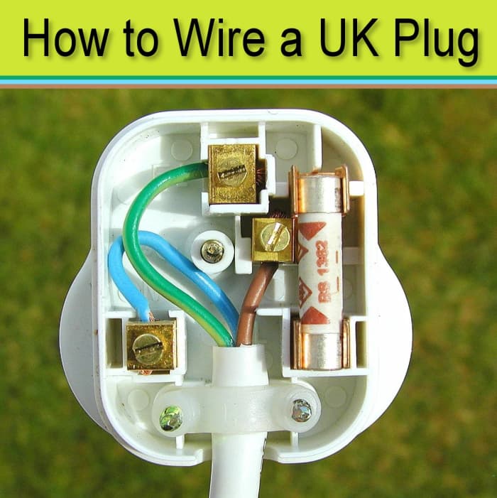
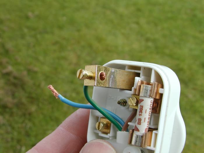
How to wire a plug. This is a UK style, BS1363 plug with integral 13 amp fuse.
© Eugene Brennan
How to Wire a UK Plug
This guide shows you how to specifically wire a UK plug to a domestic appliance. However, the same basic principles of wiring a BS1363 type plug can be applied to plugs from other countries, the main difference being that the colour-coding of wiring is different.
The first section of the guide covers some background information on the various components of a plug and an explanation of fuses, which is worth reading before making connections.
British BS1363 Standard Plug (Type G Plug)
The BS1363 standard 3-pin plug is used in the UK (England, Wales, Scotland and Northern Ireland), the Republic of Ireland, Malaysia, Saudi Arabia, Cyprus, Malta and several other countries. It's categorised as plug type G by the International Electrotechnical Commission. The plug incorporates several safety features, including a fuse to protect the power cord and equipment. It also has shrouded pins to prevent inadvertent finger contact with the live or neutral pins during insertion and removal. By law in the EU, new appliances must be fitted with a plug, however, you may occasionally need to fit a plug to an older appliance.
The Safest Plug in the World?
The BS1363 Plug is undoubtedly the safest plug in the world and has the following features:
- Fused: The primary function of the fuse is to protect the power cord/flex from overheating and possibly catching fire. The fuse will blow instantly when large short circuit currents are drawn and also when more moderate overloads occur.
- Insulated Pins: This protects inadvertent contact with live pins during insertion and removal of the plug.
- Shuttered Outlets on Sockets: This prevents children from inserting pins, nails or other metal items into socket outlets.
- Polarized: The plug cannot be inserted upside down, reversing the live and neutral.
- Long Earth Pin: This ensures that appliances are earthed during plug insertion, before the two power pins make contact.
- Grips: These are at the edges of the plug to facilitate easier removal.
- The Flex: This exits from the bottom of the plug to discourage removal by pulling on the flex.
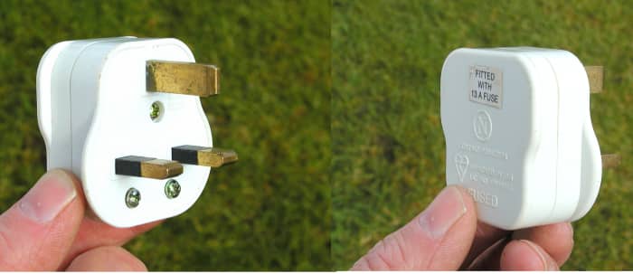
3-Pin BS1363 Plug as used in the UK and Ireland. The black plastic shrouds surrounding half the pins prevent finger contact with the pins and potential shock during insertion and removal.
© Eugene Brennan
Parts of a Power Plug
Screw terminals are provided inside a plug for connection of the wires of a power cord (flex). A UK plug has 3 square pins, live, neutral and earth as shown below. The terminals are clearly marked with the letters "L", "N" and "E".
Live and Neutral Pins
These 2 pins carry power to the appliance.
Earth Pin
Under normal conditions, no current flows through this pin. However in the event of a fault in an appliance causing the metal casing to become live, this pin acts as a "bypass", shunting current away from the user. This trips the RCD and/or MCB at the electrical panel, shutting off power. The fuse in the plug may also blow (although the RCD may trip before this occurs). The earth pin also pushes open the safety shutters covering the live and neutral entry holes in a socket outlet when the plug is inserted.
When wiring a plug, it is essential to tighten the screws firmly down onto the bared wires of each conductor. This prevents arcing, overheating and potential fire.
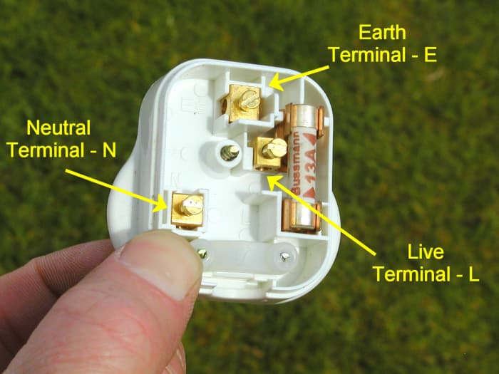
Live, neutral and earth terminals in a plug are marked L, N and E respectively
© Eugene Brennan
Fuse
A BS1363 plug is also fitted as standard with a ceramic, high breaking capacity (HBC) fuse. Its primary function is to protect the power cord from overheating caused by current overloads due to a fault or a consumer drawing too much current (e.g., connecting too many high powered appliances to an extension lead or socket strip). The fuse may also protect an appliance's internal wiring/electronics, but additional fusing is often present in the appliance to cater for this scenario. Plugs are usually supplied as standard with a 13A fuse. This is the maximum current that the plug can supply, and if an appliance tries to draw in excess of this current, the fuse will eventually blow. Fuses don't instantly blow once their current rating is exceeded. Instead they have a characteristic such that large overloads (e.g., due to a short circuit, potentially drawing hundreds or thousands of amps from the distribution transformer) will cause the fuse to blow in fractions of a second, whereas small over currents could take minutes to blow the fuse.
13A is equivalent to a load of almost 3kW at 230 volts, 50 Hertz (Hz), the EU standardised voltage and frequency.
WARNING!!
Fuses should be replaced by BS1362 standard ceramic types. These fuses have a ceramic body which can withstand the likely high current (potentially > 1000A) and energy dissipated as heat during a fault. Fuses shouldn't be replaced by types with glass bodies which can rupture.
If a lower powered appliance is connected to a plug, the fuse should be replaced by a lower rating fuse to suit the cord and appliance. 3A and 5A fuses are widely available corresponding to about 700W and 1150 watt respectively.
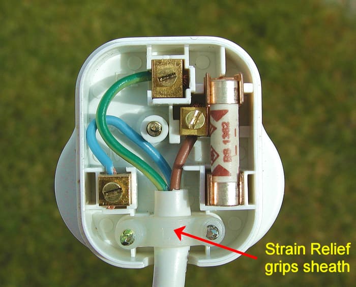
Cord Grip
A strain relief clamp or cord grip is also provided. This must be screwed down onto the outer sheath or insulation of a cable, not the inner cores. Strain relief prevents tension on the cord during normal use from pulling wires out of the screw terminals.
Read More From Dengarden
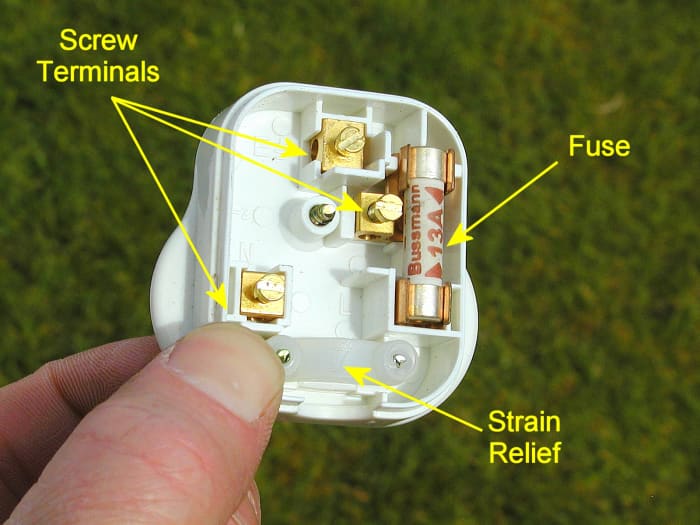
Screw terminals in a plug
© Eugene Brennan
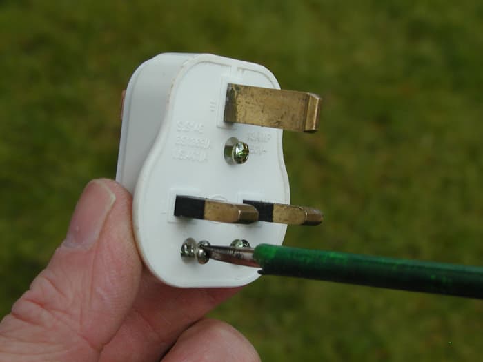
You will need:
- A flat bladed screwdriver. A phase tester is ideal and is a useful tool to have in your home toolbox. It has an internal neon bulb which can be used for detecting the presence of high voltage at socket or lighting outlets.
- A wire snips (side cutters). You could also probably use a scissors.
- A sharp knife.
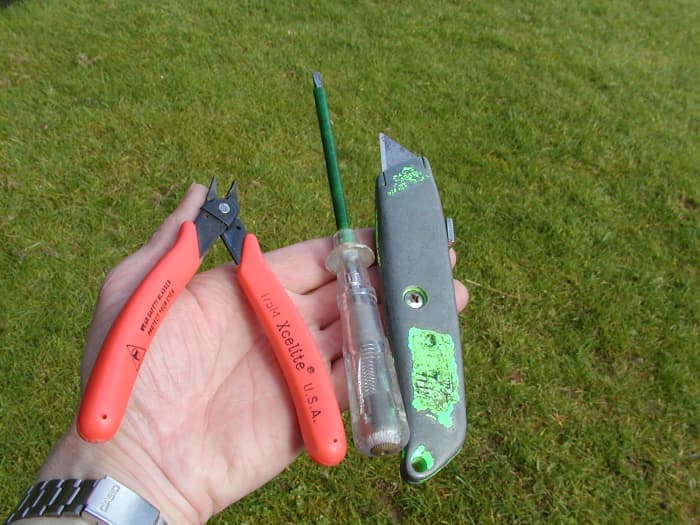
Snips, screwdriver and knife
© Eugene Brennan
Wiring Procedure
Follows these steps to wire a plug.
Step 1: Remove the Outer Sheath of the Power Cord
About 5cm or 2 inches of the sheath or outer insulation of the power cord must be removed. It is very important not to damage the insulation of the inner cores. You can snip down along the sheath if you have a snipe nose snips, alternatively score the sheath with the knife. Again you must be careful not to cut right through.
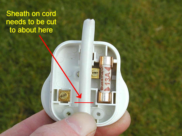
Sheath of power cord needs to be removed
Wiring Colours in the UK and EU
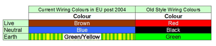
EU wiring colours and old style UK colours
© Eugene Brennan
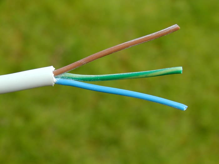
Three core flex. Live is brown, neutral is blue and earth is green/yellow.
© Eugene Brennan
What If the Flex Only Has a Brown and Blue Wire?
Doubly Insulated or Plastic Cased Appliances
Metal cased appliances normally have a three core flex attached. However, some appliances either have plastic, non-conductive casings or are doubly insulated. A double insulated appliance has a casing which, although it may still be metal, is sufficiently separated and insulated from internal live parts that there is no danger of it becoming live. These appliances are not earthed and only have a brown and blue core in their flex, i.e., no earth.
Double-insulated appliances are either marked "double insulated" or more usually the symbol below is printed on the info label.
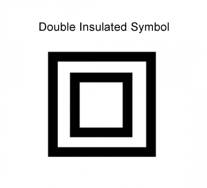
Double insulated appliances are marked with this symbol.
© Eugene Brennan
Step 2: Shorten the Live (Brown) Wire
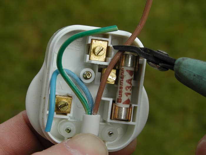
Shorten the live wire
© Eugene Brennan
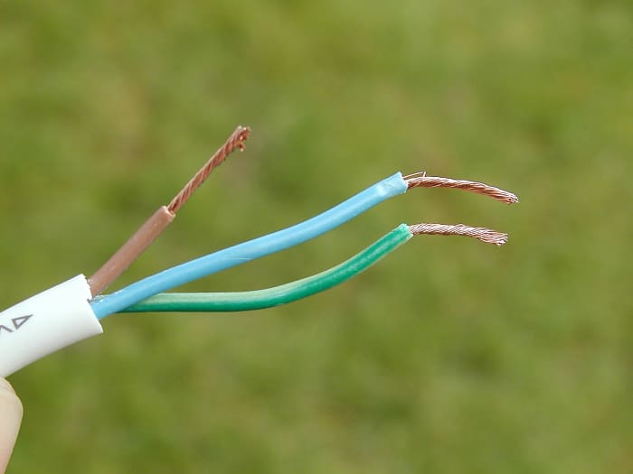
Step 3: Remove the Insulation from the Inner Cores
Remove the insulation from each conductor or core of the flex, about 10mm or just less than half an inch should be fine. You can either do this with a knife or use the snips. A snips is perfectly good as a wire stripper. With a bit of practice, all you need to do is grip the conductor, while cutting slightly through the insulation, and pull. Try this on some scrap flex first. Whichever way you bare the insulation, it's important to avoid breaking any strands of the copper conductor.
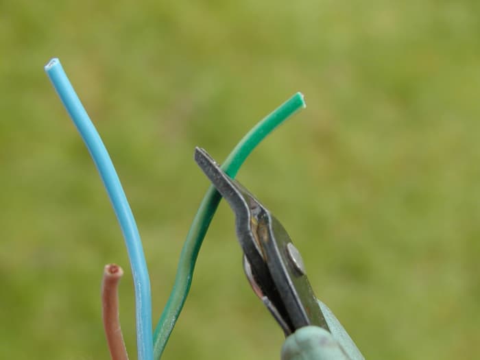
Use a knife, wire strippers or snips to strip about 12mm of insulation
© Eugene Brennan
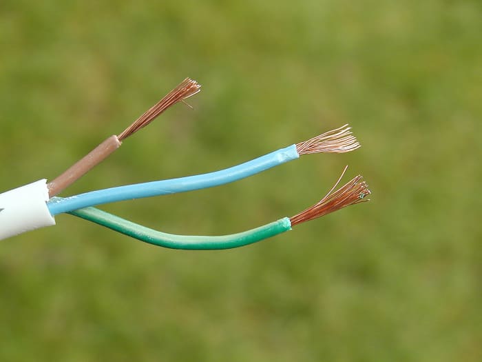
Bared conductors
© Eugene Brennan
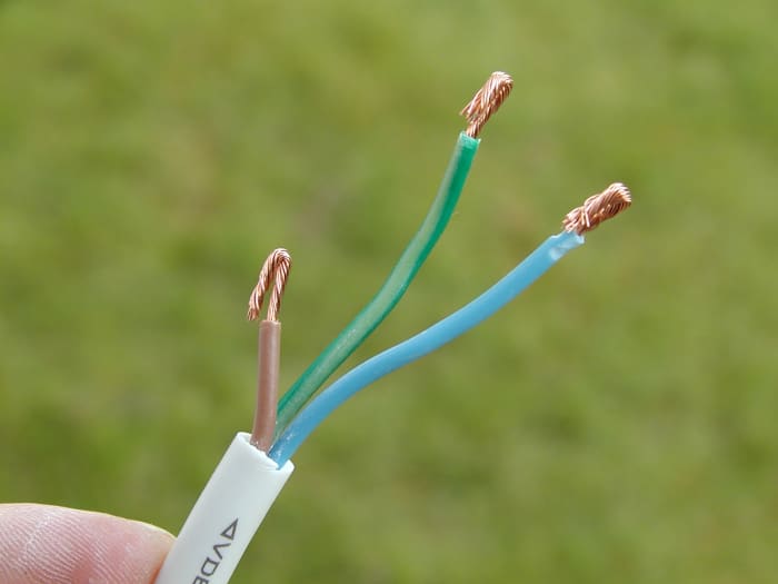
Step 4: Twist the Strands and Double Them Over
Twist the strands of each core of the flex and double them over. This keeps them together and stops them spreading out when the terminal screws are tightened. Doubling over the ends also ensures the screw has more wire to tighten down on. This is particularly important if the flex is light gage, in which case the screw may push the conductor out of the away as it is tightened, and only catch the edge of it.
Twist the stranded copper wire
© Eugene Brennan
Double over the ends of the wire
© Eugene Brennan
Choosing a Snips
Side cutters are available for cutting varying gages of cable. I have used an Xcelite side cutters, available from Amazon UK for over twenty years. The high mechanical advantage of long handles and short jaws means that they can easily snip through light to medium gage wire used in electronics. Jaws are closely spaced when closed and this is important for cleanly cutting very fine wire.

Side cutters (wire snips)
Amazon
Step 5: Loosen the Screws on the Strain Relief (Cable Grip)

The strain relief on the plug is held by two screws
© Eugene Brennan

© Eugene Brennan
Step 6: Feed the Brown Wire into the L (Live) Terminal
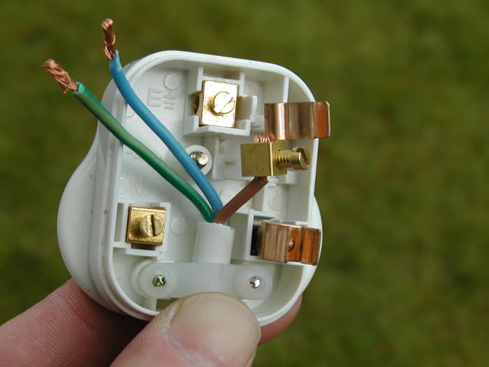
Feed the flex underneath the strain relief and push the strands of the brown wire into the terminal. It is easier to do this if you remove the fuse and terminal from the plug
© Eugene Brennan
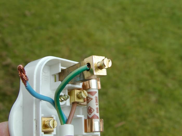
Step 7: Connect the Green/Yellow Earth Wire into the E (Earth) terminal
Some appliances don't have an earth wire in their flex
© Eugene Brennan
Make Sure the Wires Are Caught by the Screw
To avoid arcing, overheating, and in extreme cases a potential fire, it's essential to tighten screws.
© Eugene Brennan
Step 8: Finally Connect the Blue Wire to the N (Neutral) Terminal
Full wired plug - Make sure all the wires are neatly packed away so that they don't get caught by the cover or the cover fixing screw
© Eugene Brennan
Step 9: Tighten the Strain Relief and Replace the Cover
The two strain relief screws must be tightened to secure the flex.
© Eugene Brennan
Checking the Fuse in a Plug
You can check whether the fuse in a plug is ok using a multimeter. In fact, it's a good idea to have one of these in your home toolkit if you do any basic DIY. Check out my guide to using a multimeter here:
How to Use a Digital Multimeter to Measure Current, Voltage and Resistance.
For more information on electricity and an explanation of volts, amps and watts, see my guide:
How to Understand Electricity: Volts, Amps, Watts and Electrical Appliances
This article is accurate and true to the best of the author's knowledge. Content is for informational or entertainment purposes only and does not substitute for personal counsel or professional advice in business, financial, legal, or technical matters.
Questions & Answers
Question: A building is being supplied with power at 220v. The load consists of 300 lamps of 60w each and 100 fans of 40w each find (i) the total loads in kilowatts (ii) the current taken by the load ?
Answer: (i) The total load is 300 x 60 + 100 x 40 = 22,000 watts or 22 kW
(ii) To find the current, divide the load in watts by the voltage
So
Current is 22,000 / 220 = 100 amps
There's lots more examples like this on my other article here:
https://dengarden.com/appliances/Watts-Amps-Kilowa...
© 2014 Eugene Brennan
Pepenaldo panana on June 23, 2020:
what i wanted thanks
Gift on May 14, 2020:
Thanks
kudzaiishe on October 16, 2017:
tank you just what i needed
Source: https://dengarden.com/home-improvement/Wiring-a-UK-Plug
Posted by: lilliantoweryoap.blogspot.com

Posting Komentar untuk "Wiring Diagram For 9 Pin Trailer Plug"